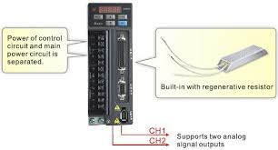
In applications where it is necessary to stop the motor servo with a minimum deceleration time, a return energy is sent from the motor to the drive, which is called regenerative energy. The return of this energy from the motor to the drive causes the voltage level of the DC link to rise and eventually leads to an overcurrent error in the drive. The intensity of the return energy depends on the inertia of the load, the speed of the motor and the time of the stop slope. The higher the load inertia and motor speed and the lower the stop time, the more energy returned to the drive, and in some cases it can even damage the drive. The solution that is usually suggested to solve this problem is to use a resistor to dissipate the return energy of the motor, which is called braking resistor.
As can be seen in the figure, the brake resistor enters the circuit only when the DC link voltage level exceeds a certain limit. In that case, the control system, which usually consists of a specific IGBT (braking IGBT) to switch the high-frequency voltage, dissipates the excess voltage on the resistor as heat.
All servo drives of Estun brand of Pronet series have internal braking resistance which is sufficient for many applications, but for applications with heavy work regime, external braking resistance should be used. If the external brake resistor is not considered for applications with high inertia or with a high number of steps/starts, an overcurrent alarm (A04) may occur, or in the worst case, when the amount of motor return energy is very high and the slope time Stop too low, alarm (A12) will appear in the drive.
Braking resistor is selected with two characteristics of power (Watt) and resistance (Ohm) for servo drives. In the table below, the appropriate resistance for some Estun drives is given in the table below:
If external braking resistor is used in Pronet drive, a jumper should be used to connect pins B2 and B3. If the external brake resistor is used, the external brake resistor must be connected between the B1 and B2 terminals by keeping the jumper between the B2 and B3 terminals. These connections are shown in the figure below.
In this method, the external braking resistance is paralleled with the internal resistance of the drive and increases the power consumption of overvoltage on the drive, and as a result, overvoltage on the DC link of the drive and related errors are avoided.
This post is written by Afkham66
